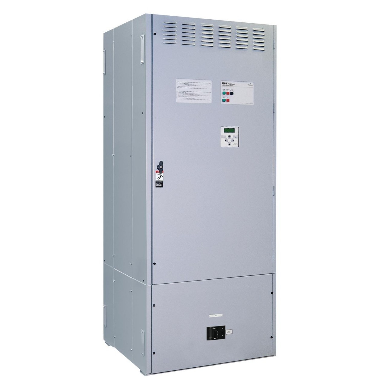
The Asco Series 7000 service entrance power transfer switch combines manual power switching with a disconnect and overcurrent protective device on the utility source. This Asco 7000SE manual (non-automatic) transfer switch is ideal for mission critical applications with three phase loads up to 4000A.
TRANSFER SWITCH FEATURES
- Electrically operated with manual control switches mounted locally or at remote locations.
- Microprocessor based controller prevents inadvertent operation under low voltage conditions and allows for addition of optional accessories.
- Low control circuit operating currents allow for long line runs between remotely mounted manual control switches and the transfer switch.
- Source acceptability lights inform operator if sources are available to accept load.
- Standard in-phase monitor can be activated for transferring motor loads.
- Reliable and field-proven solenoid operating mechanism for high speed transfer of loads.
- Conventional Open Transition (break-before-make) two-position transfer configuration. (Closed and Delayed Transition configurations available – see below.)
- Optional Bypass Isolation models available – see below.
- Programmable microprocessor controller with keypad and LCD display.
- Industrial grade user interface with integrated controls and indicating lights.
- High withstand and close-on ratings including short time withstand current rating for optimum flexibility in circuit breaker coordination.
- Front replaceable main and arcing contacts.
- Standard ground conductor connections.
- Four auxiliary contacts, two contacts closed when switch is in normal position and two contacts closed when switch is in emergency position.
- Centrally located terminal block for all customer control connections.
- Main Terminals are rear connected.
- Local/remote communications capability for interfacing with ASCO PowerQuest® communication products.
- Options of solid, switched, or overlapping neutral conductor – see below.
- UL 1008 Listed and CSA Certified.
- Enclosures are free-standing with removable top, sides, and back. NEMA 1 indoor enclosure standard (other options available – see options below).
SERVICE ENTRANCE FEATURES
- Meets all National Electric Code requirements for installation at a facility’s main utility service entrance.
- Generally are installed at facilities that have a single utility feed and a single emergency power source.
- Ground fault trip protection provided.
- Insulated case circuit breaker offers utility disconnect and overcurrent protection.
- Standard Ampere Interrupting Capacity (AIC) Rating of 100kA.
- Disconnect link on Neutral.
- Disconnect link on Ground.
- Ground and Neutral Bus – all silver-plated copper.
- Solderless screw type terminals for External Power Connections.
- Internet enabled monitoring and control.
- UL 891 Listed.
- See Asco 7000 Brochure p8-9 for further details.
CONTROL FEATURES
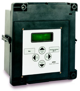
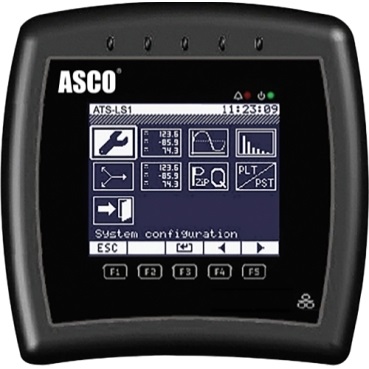
Asco Series 7000 Microprocessor Controller
 Advanced digital microprocessor.
- Voltage, frequency, control, timing, and diagnostic functions.
- Microprocessor logic board is separated and isolated from the power board to improve electrical noise immunity performance and assure compliance with rigorous transient suppression standards.
- Allows the user to easily access detailed information on: system, power source parameters, voltage, frequency and time delay settings, optional feature settings, historical event log, and system diagnostics.
- A four line, 20 character LCD has a backlit display which enables easy viewing under all conditions (see Asco 7000 Brochure below for screen shots).
- All screens can be navigated using only six buttons.
- Touch pad programming of features and settings without the need for meters or variable power supplies.
- On-board diagnostics provide control panel and ATS status information to analyze system performance.
- Displays and counts down active timing functions.
- Selectable multi-language display (English, German, Portuguese, Spanish, or French).
- Password protection to prevent unauthorized tampering of settings.
- For more detailed information, see 7000 Series Microprocessor Controller.
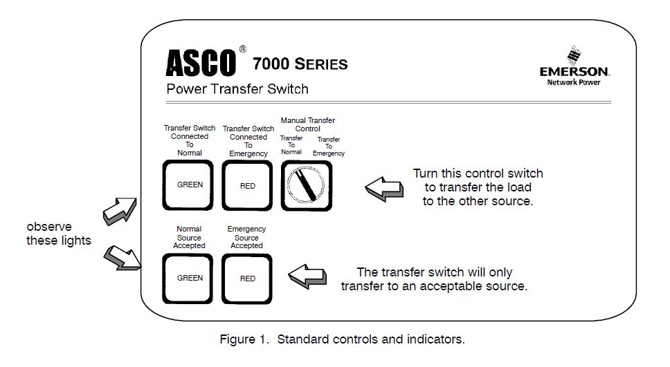
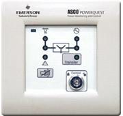
Asco Series 7000 User Interface
- Manual transfer control switch for transferring load from normal to emergency, and back again.
- Switch position indicating lights (16 mm, industrial grade LEDs).
- Source acceptability indicating lights with true indication of the acceptability of each source, as determined by the voltage, frequency, voltage unbalance, and phase sequence settings of the control panel (16mm, industrial grade LEDs).
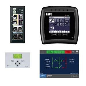
- See diagram in the pictures above for layout.
Closed Transition Option
- Features main contacts that overlap, permitting the transfer of electrical loads without power interruption.
- Transfers in a make-before-break mode if both sources are within acceptable parameters.
- Control logic continuously monitors source conditions and automatically determines whether the load transfer should be open (conventional non-overlap mode) or closed transition.
- Closed-Transition transfer within 5 electrical degrees is achieved passively, without control of the engine generator set.
- No additional control wire runs are required between the ATS and engine generator set governor.
- Protective relaying may not be required under normal operation since the contact overlap time is less than 100 milliseconds (consult your local utility on protective relay requirements).
- Extended parallel time protection standard. User interface provides visual indication when the pre-set extended parallel time has been exceeded. The controls automatically open the emergency or normal main contacts. Separate contact also available to shunt trip to an external breaker.
- Failure to synchronize indication standard. User interface visually displays a failure to synchronize alarm if the time delay settings is exceeded, during closed transition transfer operation.
- Transfer switch lock out with user interface indication standard. Prevents transfer in either direction if the extended parallel time is exceeded.
- User interface alarm reset button. Resets extended parallel and failure to synchronize alarms.
- Closed Transition bypass pushbutton on user interface allows transfer between sources in an open transition mode.
- Please see the Asco 7000 Brochure below for withstand ratings (p5), screw-type terminal connections (p22), and dimensions/weights (p9).
Delayed Transition Option
- Designed to provide transfer of loads between power sources with a timed load disconnect position for an adjustable time period.
- Applications include older style variable frequency drives, rectifier banks, and load management applications.
- Utilizes reliable, field proven solenoid operating mechanisms.
- Mechanical interlocks to prevent direct connection of both sources.
- Indicator light (LED type) for load disconnect position.
- Adjustable time delay for load disconnect position.
- Please see the Asco 7000 Brochure below for withstand ratings (p5), screw-type terminal connections (p22), and dimensions/weights (p9).
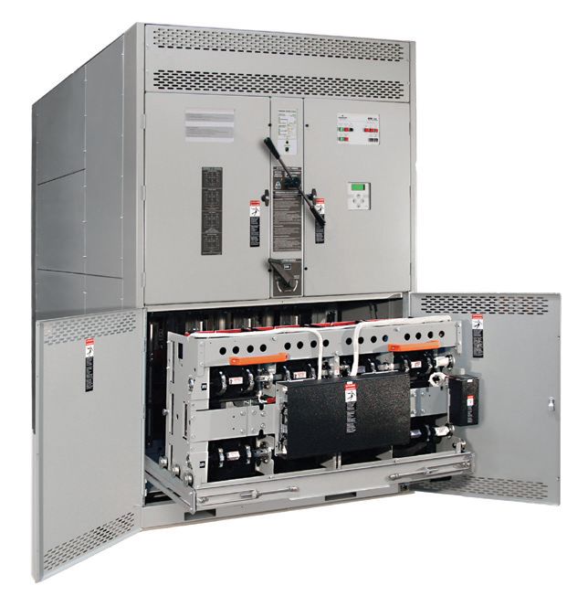
Bypass Isolation Option
- Available in Open Transition, Closed Transition, and Delayed Transition configurations.
- Allows the primary transfer switch to be inspected, tested, and maintained without any interruption of power to the load.
- Provides redundant power transfer in the event the transfer switch is disabled or removed from service.
- Bypass switch and transfer switch have identical electrical ratings.
- Heavy duty mechanical interlocks prevent undesirable operation.
- Bypass contacts carry current only during bypass mode.
- Transfer switch is drawout design for ease of maintenance (see p6 of the Brochure below for details).
- Bypass and isolation handles are permanently mounted. The bypass switch has dead front quick-make, quick-break operation for transferring of loads between live sources.
- Bypass switch is fully rated for use as a manual 3-position transfer switch.
- Bypass and isolation functions are simple, requiring a total of two operating handles.
- No toggle switches, push buttons, selector switches or levers are required for bypass-isolation operation.
- Mechanical indicators show bypass and transfer switch positions.
- For more information and visual demonstration, please see these Asco 7000 Bypass Isolation videos.
- Please see the Asco 7000 Brochure below for diagrams (p7), withstand ratings (p5), and screw-type terminal connections (p22). Please call for dimensions and weight information.
PRODUCT DOWNLOADS
Asco 7000 Microprocessor Controller
NEUTRAL OPTIONS
- Solid neutral with fully-rated terminals. (AL-CU) UL Listed.
- Conventional neutral switching pole.
- Overlapping neutral transfer contacts. Allows for proper ground-fault sensing and avoids generator voltage transients during transfer.
TRANSFER SWITCH OPTIONS
- Other 50/60 Hz voltages up to 600 VAC.
- Other Enclosures: NEMA Type 3R secure double door, NEMA 3RX secure double door (stainless steel).
- Extended Warranties.
OPTIONAL ACCESSORIES
Time Delays
- Accessory 2C – Provides an extended time delay on engine starting. The standard feature one time delay is adjustable from zero to six seconds. Accessory 2C allows this time delay to be adjustable from zero to sixty minutes in one second intervals factory set at five minutes.
- Accessory 1G1 – Similar to accessory 2C except using 24 volt DC external input signal. Controls, metering and communication remain remains active when both power sources are de-energized.
- Accessory 1GB1 – Same as accessory 1G1 except using 120 volt AC external input.
- Accessory 1PS1 – Extended control power ride-through (approx. 25 seconds) for Group 5 ATS controller and select communications and metering accessories including 72EE2 and 135L.
Indicators
- Accessory 14A/14B – Additional auxiliary contact sets to indicate switch position. Two sets are standard. Specify total number of sets if more are required.
- Accessory 18B – Two-pole, double-throw contacts operate when emergency source voltage is present at transfer switch terminals.
- Accessory 18G – Two-pole, double-throw contacts operate when normal source voltage is present at transfer switch terminals.
- Accessory 99 – “Push-to-Test” feature on all pilot light indicators.
Customer Control Circuits
- Accessory 30A – Load-shedding circuit initiated by opening of a customer-supplied contact.
- Accessory 30B – Load-shedding circuit initiated by removal of customer-supplied control voltage. (Specify voltage).
- Accessory 31Z – Selective load disconnect control contacts (two provided) which operate with time delay prior to and/or after load transfer and retransfer.
Extension Harness
- Accessory 37B – Six foot (6’) extension harness to increase distance between transfer switch and control panel on open-type units.
Surge Protection
- Accessory 73AC1 – ASCO 510 TVSS rated 65KA. Normal source protection. (3Ø, 4wire WYE)
- Accessory 73AC2 – ASCO 510 TVSS rated 65KA. Emergency source protection. (3Ø, 4wire WYE)
- Accessory 73AC3 – ASCO 510 TVSS rated 65KA. Load side protection. (3Ø, 4wire WYE)
Service Entrance Applications
- Strip Heater – With thermostat.
- Connections – Crimp lugs.
- Connections – Bus Riser on Normal, Emergency, or Load.
- Additional Breaker – Circuit Breaker on Emergency.
- Additional Breakers – Load Distribution Panel.
Bypass Isolation Accessories
- Accessory 14A1 – Auxiliary contact to close in “Bypass to Normal” position.
- Accessory 14B1 – Auxiliary contact to close in “Bypass to Emergency” position.
- Accessory 14T – Auxiliary contact to close when transfer switch is in “Automatic” position.
- Accessory 14U – Auxiliary contact to close when transfer switch is in “Isolate” position.
- Accessory 14V – Auxiliary contact to close when transfer switch is in “Test” position.
- Accessory 82E – LED Bypass status indicator, optional on G frame 1600 to 4000 amps only. Standard for all other size switches.
Special Applications
- Accessory 45 – Custom Alphanumeric nameplate mounted on the front of the switch.
- Accessory 111A – Generator – to – Generator for Standby Applications.
- Accessory 111B – Generator – to – Generator for Prime Power Applications.
- Accessory 125A – Seismic Certification to the requirements of the International Building Code for electrical equipment.
- Accessory 131 – Certification of compliance with the American Recovery & Reinvestment ACT (Buy American Provision) – Must be specified at time of order placement.
Communications/Metering (See Accessories Tab)
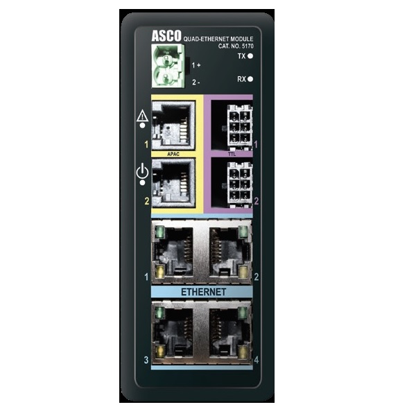
- Accessory 72EE2 Ethernet Connectivity Module 5170 – Offers remote Ethernet monitoring via open Mod bus and SNMP protocols, email notifications and embedded monitoring web pages.
- Accessory 107G Monitoring Gateway – Provides Building Monitoring Systems with transfer switch, bypass and load power metering information in Modbus TCP/IP, BACnet IP and SNMP Protocols. (Requires 72EE2 or 150A/B)
- Accessory 135L Power Meter 5210 – Offers local monitoring of power and energy information on the Asco 7000 load side.
- Accessory 140L Power Meter 5400 Series – Continuously records waveforms at high-speed and identifies transients, sags/swells and harmonics. Installation examples include generators, utility mains, transfer switches, UPS systems, paralleling gear, TVSS, PDUs, and critical power distribution switchboards.
- Accessory 150A/B Tech Package – Includes Accessory 1PS1 UPS with extended 25 second ride through for ATS controller/135L/72EE2, Accessory 72EE2 Connectivity Module 5170, Power Meter 5210 or 5400 Series, CTs, and Shorting Blocks. 150B includes Bypass Status Monitoring via discrete I/O (for Bypass Transfer Switches).
- Accessory 150AT/BT Tech Package with Touch Diplay Interface – Includes Accessory 1PS1 UPS with extended 25 second ride through for ATS controller/135L/72EE2, Accessory 72EE2 Connectivity Module 5170, Power Meter 5210 or 5400 Series, Touch Display Interface (TDI), CTs, and Shorting Blocks. 150B includes Bypass Status Monitoring via discrete I/O (for Bypass Transfer Switches).
Remote Monitoring and Control (See Accessories Tab)
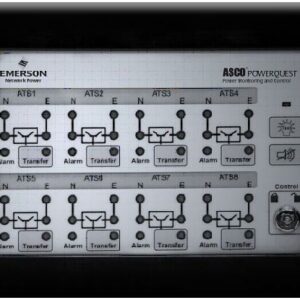
- Single Channel 5310 Remote Annunciator – Provides remote monitoring and control of one Asco 7000 transfer switch. Requires Accessory 72EE2.
 Eight Channel 5350 Remote Annunciator – Provides remote monitoring and control of up to eight Asco 7000 transfer switches. Requires Accessory 72EE2.
- Eight Device 5705 Remote Annunciator – Provides remote monitoring and control of up to eight devices via Ethernet, RS485, and Discrete Inputs. Applicable devices include transfer switches, engine-generator, load banks, and surge protection systems. Integrates with Building Monitoring Systems and automatically generates NFPA test reports as needed.
- PowerQuest 5710 Essential Critical Power Management System – Offers monitoring and control of up to 32 devices from a web browser accessible server with a 22 inch touchscreen.
- PowerQuest 5750 Professional Critical Power Management System – Offers monitoring and control of up to 64 devices from a web browser accessible server with a 22 inch touchscreen.
- PowerQuest 5790 Enterprise Critical Power Management System – Offers monitoring and control of up to 128 devices from a web browser accessible server with a 22 inch touchscreen.
- PowerQuest 5900 Custom Critical Power Management System – Offers the ultimate in monitoring and control customization, redundancy, and scalability.
Other options may be available. Please call to inquire.

Reviews
There are no reviews yet.